|
||||||||||||||||||||||||
Meshdynamics has been talking about multi-radio and multi-frequency mesh since 2002 but there has been confusion about what "multiple-radio" means, and how the patented Meshdynamics approach is different from others. This paper analyses the relative performance of 3 competing mesh architectures: a single radio ad-hoc architecture, a dual-radio architecture with a single radio ad-hoc mesh backhaul, and a three-radio- structured mesh backhaul unit We explain why the 3-radio system provides far better bandwidth distribution than other competing architectures. We describe in detail how with merely 5 simultaneous clients per mesh node, both the single radio ad hoc and the dual-radio, single radio mesh architectures cannot provide usable bandwidth (for voice/video) beyond 2 hops and the implications of these limitations. Finally, we describe why a three-radio Meshdynamics architecture is not subject to such limitations. This is what makes Structured Mesh the most efficient means of operating VOIP phones or IP Video over a mesh network or any significant scale. 
 Fig. 1: Single radio backhaul (hub) and the Meshdynamics wireless emulation of switch stacks Fig. 2: Competing mesh products suffer from Bandwidth loss with each hop Before beginning this discussion of mesh architectures, it is useful to define some terms that will be used throughout the paper. Figure 1 shows two types of meshed networks. On the left is the most common configuration with a single backhaul radio and on the right is a Meshdynamics 3-radio MD4350. These types will be described in more detail later, but both have certain similarities. Both must connect, at some point, to a higher speed data network. In most cases this is a wired network, such as an Ethernet network, but this is not necessarily the case. For our purposes, however, we will refer to the high speed data network as the "wired network." At least one node making up the mesh must bridge to that wired network, and we refer to that mesh node as a "root" of the mesh. The mesh network itself is made up of different radio devices, known as nodes. Radios on the mesh nodes have two functions to fulfill. First, they must provide service to the clients that want access to the services available on the wired network. Second, they must provide a path for information from those clients to the wired network, and vice-versa. The provision of this path to the wired network is referred to as the "backhaul" service. In some cases (the ad hoc mesh network) a single radio provides both services. In other cases (e.g. Meshdynamics) more than one radio is used. Modern mesh network requirements have evolved from their military origins as mesh networking moved from the battlefield to the service provider, enterprise, and residential networking environments. Today, Internet connectivity is needed more than local peer-to-peer connectivity. Data sources are primarily resident on the Internet, not on a peer. Also, to cover large areas in a cost-effective way, nodes may be placed further away from their eventual connection to the wired network, which implies more relay or "hops" within the mesh until the Ethernet cable (wired network) is reached. These new requirements highlight the inherent limitations of conventional, ad-hoc, mesh networks. In an ad-hoc mesh network there is one radio channel on which all nodes communicate with each other. For data to be relayed from mesh node to mesh node it must be repeated in a store-and-forward manner. A node first receives the data and then retransmits it. These operations cannot occur simultaneously because, with only a single radio channel, simultaneous transmission and reception would interfere with each other. This inability to simultaneously transmit and receive is a serious disadvantage of the ad-hoc mesh architecture. Simply put, if a node cannot send and receive at the same time, it loses ½ of its bandwidth as it attempts to relay packets up and down the wireless backhaul (relay) path. A loss of ½ with each hop implies that after 4 hops, a user would be left with (½*½*½*½) = 1/16 of the bandwidth available at the Ethernet link. This is a 1/(2N) relationship where this equation defines the fraction of the bandwidth that is available to a user after N hops. There has been much argument on the validity of this 1/2N bandwidth degradation claim. Mesh providers do concede that their products suffer from bandwidth degradation with each hop (Figure 2). But some claim that if the hops between mesh nodes are large enough in distance, there could be simultaneous conversations along a path through the mesh and that bandwidth degradation is closer to 1/N than 1/2N. An independent study indicates a degradation of 1/(1.68)N for typical single radio backhaul topologies. However, for the sake of this analysis, we shall continue to use the more conservative 1/N scaling factor 
 Fig. 3: competing mesh architectures (L-R): Ad Hoc, 1-Radio Meshed Backhaul, Multi-radio Mesh Fig 4. Involuntary Bandwidth Sharing -Clients get a piece, of a piece, of total available bandwidth (1/3.. 1/9.. 1/27) . Three competing mesh architectures are shown above. They are, from left to right: 1. 1-Radio Mesh. As shown on the left, this network uses one radio channel both to service clients and to provide the mesh backhaul. The single mesh radio, marked AH, provides both services - client access and backhaul. The comparative performance analysis to follow indicates this architecture provides the worst services of all the options , as expected- both backhaul and service compete for bandwidth. 2. Dual-Radio with a 1-Radio backhaul mesh. This configuration can also be referred to as a "1+1" network, since each node contains two radios, one to provide service to the clients, and one to create the mesh network for backhaul. The "1+1" appellation indicates that these radios are separate from each other - the radio providing service does not participate in the backhaul, and the radio participating in the backhaul does not provide service to the clients. These two radios can operate in different bands. For example, a 2.4 GHz IEEE 802.11 b/g radio can be used for service and an IEEE 802.11a (5 GHz) radio can be used exclusively for backhaul. Competing mesh products typically fall into this category. Separating the service from the backhaul improves performance when compared with conventional ad hoc mesh networks. But since a single radio mesh is still servicing the backhaul, packets traveling toward the Internet share bandwidth at each hop along the backhaul path with other interfering mesh backhaul nodes - all-operating on the same channel. This leads to throughput degradations which are not as severe as for the single radio mesh, but which are sizeable nevertheless. 3. 3-Radio Meshdynamics MD 4350 The last architecture shown is one that provides separate backhaul and service functionality and dynamically manages channels of all of the radios so that all radios are on non-interfering channels. Performance analysis indicates that this provides the best performance of any of the methods considered here. Note that the two backhaul radios for the 3-radio configuration shown in Figure 3 are of the same type - not to be confused with 1+1 so-called dual radio meshes where one radio is typically of type A (backhaul) and the other of type B/G (service). In the 3-radio configuration, 2 radios provide up link and down link backhaul functionality, and the other radio provides service to clients. Wireless is a shared medium. Radios communicating on the same channel and within range of each other will contend for available bandwidth. How this contention manifests itself differs depending on the radio protocol. In some cases contending nodes may degrade the noise floor, reducing rate, range, or both. In other cases, the nodes may literally prevent each other from using the channel. This is the case with devices based on the IEEE 802.11 suite of standards, which share bandwidth based on collision avoidance rules known as carrier sense multiple access with collision avoidance (CSMA/CA). Bandwidth reduction - caused from bandwidth sharing - limits backhaul traffic at each hop and is compounded at each hop. If there are C simultaneous clients per mesh node, packets coming from the client at the mesh node farthest from the backhaul have a 1/C bandwidth share as they attempt to reach the closest mesh node. Aggregated traffic from this node gets a 1/C share again as it attempts to reach the next mesh node. The bandwidth share for the original packet is now 1/2C . This compounding continues: (1/2C.. 1/3C .. 1/4C) until the Ethernet backhaul is reached. Thus, in the case of single 1-Radio mesh with just 2 clients (since the mesh node is effectively another client) the bandwidth degradation per hop follows the 1/NC effect: 1/3 .. 1/9 .. 1/27. So clients get a piece, of a piece, etc of the total available bandwidth (1/3.. 1/9.. 1/27) . Thus conventional single radio is useless beyond 2-3 hops for applications requiring either significant bandwidth or low latency. (Latency and bandwidth are inversely related- the thinner the pipe, the longer it takes for data to flow through it). Dual radio systems have a separate service radio in addition to the backhaul radio that participates in the single radio mesh. Clients attaching to the service radio contend with each to share service radio bandwidth. Data enters the service radio and is transferred over the backhaul mesh through a bridge. When client packets transfer to the backhaul radio, they are subject to contention (involuntary bandwidth sharing) with neighboring mesh radios. Recall that even in these dual radio systems, all backhaul mesh nodes are using the same channel. How many neighboring 1+1 mesh nodes are in contention depends on the mesh topology. In the urban grid model shown (Figure 4), communications must traverse the "Urban Canyons" - tall buildings between blocks. If the nodes are placed at road intersections, then nodes are in range of at least 3 other nodes. At peak times - when all nodes are trying to move packets at the same time - each 1+1 mesh backhaul radio receives 1/4 of available bandwidth - there are a total of 4 nodes involuntarily sharing the same radio medium (recall all the mesh backhaul radios have to be on the same channel). Involuntary bandwidth sharing for the 1+1 mesh in an Urban Grid Topology is 1/4 .. 1/16 .. 1/64 etc. All Meshdynamics nodes operate on non-interfering channels. Hence it does not suffer from involuntary bandwidth sharing. 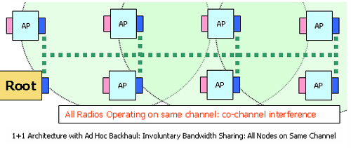 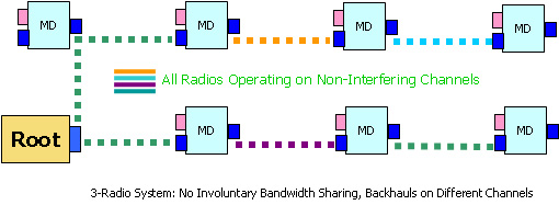 Fig. 4 left: Urban Grid Topology - Dual (1+1) Radio Mesh Fig. 5 right: Urban Grid Topology - Meshdynamics Third Generation Structured MeshTM
We now compare performance for the 3 mesh architectures: 1. First Generation: 1-radio mesh with a single 802.11b radio for Backhaul and client access |