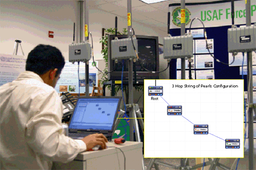
Figure 1: (Left) Test Set up of 3-Radio modules Figure 2: (Right) Connectivity diagram of
MD4350 3-Radio nodes.
The
MD4350 3-Radio
Mesh Module was tested at the US Air Force Force Protection
Labs and with approved network performance measuring
equipment. The MD4350 3-Radio contains two 802.11a radios for
backhaul and one 802.11b/g service radio.
Specs
 TEST
#1: Bandwidth preservation over
hops. After much debate, it was conceded that the performance of single radio mesh networks degrades between 1/n (in the best case) and (1/2)n (typical case) with each hop away from the Ethernet feed. Meshdynamics claimed that since we use a third generation backhaul it has minimal degradation with each hop. To validate these claims, each Mesh node was isolated in such a way that it will only "see" the mesh node as indicated above. Throughput at each hop and the bridge delay per hop was measured. Throughput was measured by using IXIA Test Software. The introduced delay was measured by using pings.
The results are depicted in Table 1. Note: These are TCP/IP numbers, not raw data rate numbers.
TEST
#1: Bandwidth preservation over
hops. After much debate, it was conceded that the performance of single radio mesh networks degrades between 1/n (in the best case) and (1/2)n (typical case) with each hop away from the Ethernet feed. Meshdynamics claimed that since we use a third generation backhaul it has minimal degradation with each hop. To validate these claims, each Mesh node was isolated in such a way that it will only "see" the mesh node as indicated above. Throughput at each hop and the bridge delay per hop was measured. Throughput was measured by using IXIA Test Software. The introduced delay was measured by using pings.
The results are depicted in Table 1. Note: These are TCP/IP numbers, not raw data rate numbers.
|
No of Hops from Root
|
Throughput (Mbps)
|
Bridge Delay (ms)
|
|
1
|
22-23 Mbps TCP/IP (54 Mbps Raw)
|
Less than 1 ms
|
|
2
|
22-23 Mbps TCP/IP (54 Mbps Raw)
|
Less than 2 ms
|
|
3
|
22-23 Mbps TCP/IP (54 Mbps Raw)
|
Less than 3 ms
|
Fig 2: Latency Scales across hops.
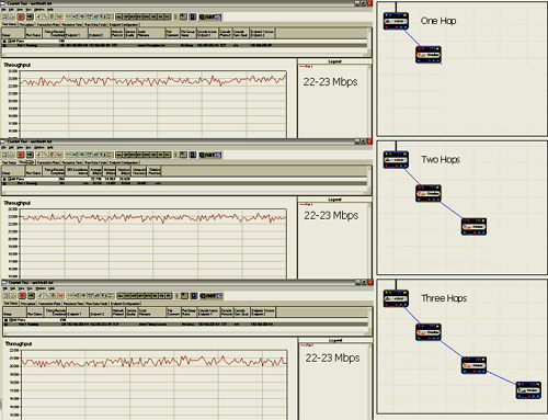
Figure 3: TCP/IP throughput measured at 1, 2 and 3 hops (3-Radio Structured Mesh).

Figure 4: Bridge Latency measured at 3 hops is less than 3 ms. (3-Radio Structured Mesh).
TEST
# 2: Bridge Latency over hops Latency sensitive transmissions (e.g. VOIP and Video streams over mesh) , are affected by the delay in wireless bridges. Recall that in the 3-radio Structured Mesh modules, there are dedicated service and backhaul radios. All data passes from the service radios to the backhaul radios via a high speed low latency wireless switch/router implemented in each Structured Mesh module. Over multiple hops, the latency introduced by the wireless bridge could be significant. This adversely affect both VOIP & Video. As shown in Figure 4, the bridge latency introduced - at the last hop - was noted to be less than 3 ms. Further testing
confirmed a bridge delay of ~0.5-0.7 ms per hop for
Meshdynamics backhauls..

Figure 5: Meshdynamics mesh nodes
rapidly self heal. |
TEST
# 3: Rapid Self-Healing of the Mesh. A critical characteristic of high performance mesh networks is their ability to self configure rapidly in the event of node failure. One of the nodes was shut off - the system configured itself in less than 2 seconds. Note: The delay is based on a sampling interval to decide if a node is indeed "down". It is adjustable. The tests were conducted later with a lower sampling interval. The self healing time was recorded at 0.7 seconds.
Figure 6:Test Setup to see Mesh topology changing to support latency/throughput requirements.
TEST
#4: Dynamic control of mesh topology. The control layer is designed to automatically change the mesh topology when the signal strength changes between mesh nodes and connectivity performance is adversely affected. To demonstrate the adaptive control over mesh topology a signal attenuator gradually changed the signal strength, thereby forcing the adaptive control layer to take action. The switch from the dotted connection to the solid line connection ( Figure 7) occurred within one second of reaching the thresholds where bandwidth connectivity was adversely affected.
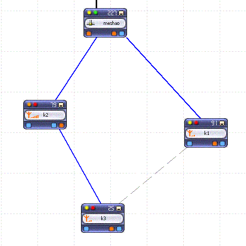
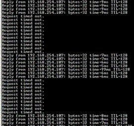
Figure 7: (left) How Mesh topology changed to support latency/throughput requirements.
Figure 8: (right) Automatic Switching channels to mitigate interference
TEST
#5: Dynamic Interference Avoidance on a segment basis. One advantage of the multiple radio system is that each node operates on a different channel and interference is thus contained - since interference effects are restricted to one segment of the mesh. This is a distinct advantage of the multiple radio system over single radio approaches. This test demonstrated how the system reacts to interference on one channel- the mesh node switches to another backhaul parent, operating on another (interference free) channel, to manage connectivity performance in a proactive manner. An interferer was injected after node 2 in a 4 hop 2 radio Structured mesh network. The signal became so low that node 1 switched to node 3. The time was measured between the time instance the SIR reduced and the channel switching time from node 1 to node 3. A typical screen capture is shown in Fig. 8. The test was repeated three times to determine if the behavior was repeatable and consistent.
Summary:
Meshdynamics multi-radio backhaul nodes provide distinctive advantages over traditional single radio
backhauls:
1) Minimal degradation of bandwidth or latency over multiple hops.
2) Ability to modify mesh topology to meet dynamic performance requirements of latency/throughput
3) Ability to switch to other channels to mitigate interference effects in one part of the network.
 Web
Page MD4000 Products Page. (Overview of our product, Network
Management System, Configuration options)
Web
Page MD4000 Products Page. (Overview of our product, Network
Management System, Configuration options)
Web
Page MD4000 Model Configuration. (Overview of our model
configurations and their applications)
Web
Page Frequently Asked Questions. (On Antenna selection, GPS,
Mobility extensions, Hazard proof enclosures)
